Master Model Railroader

"An NMRA member qualifies as a Master Model Railroader when he or she has obtained at least seven of the eleven Achievement Certificates provided that he or she has earned at least one Achievement Certificate in each of the four areas of the Regulations. Earning the title of Master Model Railroader is the ultimate goal for many participants in the Achievement Program."

Tuesday, September 17, 2013

Model Description (sample)

This is my written description of how I've built the bridge for the Master Builder Structures Certificate. I have written similar descriptions for all of my models although less might be sufficient. The important thing to remember is to point out special features or methods that are probaly not evident to the judges. A list of all commercial parts is always required and should be as complete as possible.
Photos of the prototype and drawings that were used to build the model must also be included.

***


BRIDGE for a country road

  1. CONSTRUCTION

      To build the bridge I:

-          followed a drawing from the Kalmbach book “Bridges and Trestles”
-          Cut and fit stripwood with a NWSL chopper
-          Scratchbuild and weathered

First I weathered all wood parts with a wash of diluted India ink.

After the weathering had dried I cut the bridge planks to size and placed them side-by-side on a piece of tape glue.

Then I cut the supporting beams to length and glued them equally spaced to the planks.

Then I cut the beams for the triangular bridge truss, bevelled the ends and glued the pieces together in a jig.

After the bridge assembly was dry I glued a plank 16 scale inches longer than the bridge planks on either side of the bridge for support of the truss assembly.

I cut the kingpost beam to length and glued it in the center of the bridge.

After the truss assembly was dry, I glued both parts to the support planks and centered everything over the kingpost.

The bridge is held together with metal rods and stringers.

I simulated the different iron straps and plates with small pieces of strip styrene

I drilled appropriate holes and threaded brass wire through the holes to simulate the different rods as per the drawing.

  1. DETAIL

      To visualize the bridge, I mounted it on a small display. I cut 2 pieces of wood for the       abutments and fixed Faller Decorative Sheets “Natural Stone” to theses abutments to represent         the random stone pattern. Then I shaped pieces of Styrofoam to represent the sloped terrain. I      covered the scene with different scenery materials. A small riverbed adds to the purpose of the         bridge.

      Parts list

      Northeastern Scale Lumber     3014    2 x 8
                                                     3041    6 x 8
                                                     3034    4 x 12
                                                     3043    6 x 12

      Detail Associates                    2507    0.015” brass wire
                                                     2505    0.010” brass wire
                                                     2506    0.0125” brass wire
                                                     2206    Eyebolts

      Woodland Scenics                              Fine turf

      Faller                                      170802            Decorative Sheets “Natural Stone”

      Miscellaneous                                     strip styrene pieces
                                                                 Tile mortar for ground cover
                                                                 Sifted Sand and different sizes of gravel
                                                                 Two component epoxy for the water  

  1. CONFORMITY

      This bridge was located somewhere in Ohio. These wood bridges of the kingpost truss type           were common years ago in rural areas but are rapidly becoming scarce because of age, fires, floods and ice jams.

  1. FINISH AND LETTERING

      I treated the wood stock with a wash of diluted India ink. I also punched nail holes into the           planks using a punching wheel.

  1. SCRATCHBUILDING

      The bridge is completely scratchbuild using different sizes of scale lumber and brass wire.

Model Railroad Engineer - Electrical (Requirements)


Electrical

Model Railroad Engineer - Electrical

The requirements for Model Railroad Engineer - Electrical may look long and complicated, but they are not really. The reason that they are so long is to offer you more options for meeting the requirements.
You don't even have to do all of the work on a single layout - you can do some on a club layout, some in your basement, and some on your garden railroad, etc.
Remember - don't make the requirements more difficult than they are, by reading more into them than is there.


To qualify for the Model Railroad Engineer - Electrical certificate, you must:

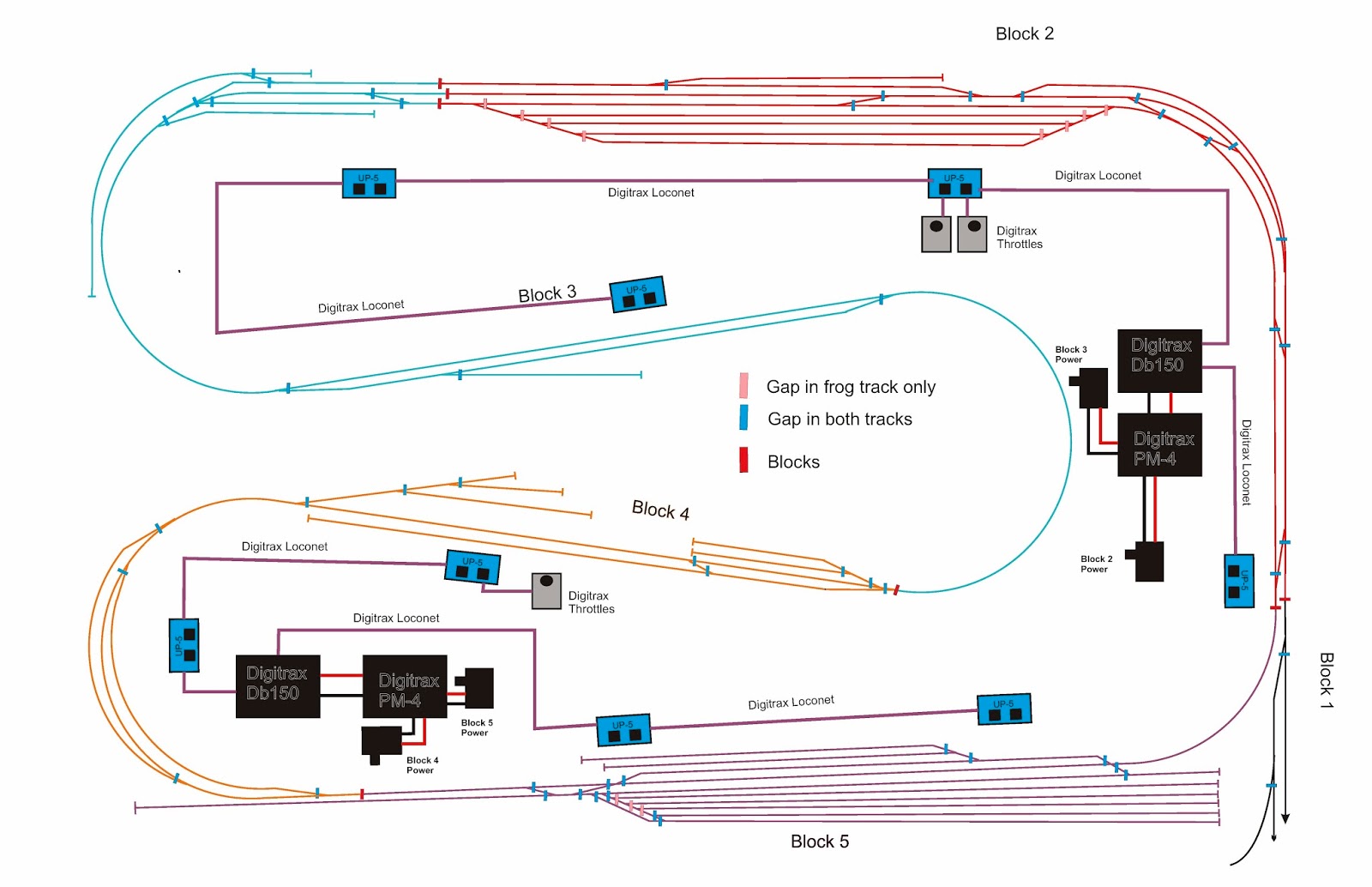
A. Construct and demonstrate on own or club layout, the satisfactory operation of an electrical control system on a model railroad capable of simultaneous and independent control of two mainline trains in either direction, and containing at least:
1.      For conventional DC wiring (non-command-control), five electrical blocks that can be controlled independently. For command control wiring (DCC, TMCC, and others), sufficient gaps and switches to maintain polarity, phase if needed, and troubleshooting.
2.      One mainline passing siding.
3.      One reversing loop, wye, turntable, or transfer table.
4.      One yard with a minimum of three tracks and a switching lead independent of the main line.
5.      Facilities for the storing of at least two unused motive power units
6.      One power supply with protective devices (short indicator or circuit breaker) to ensure safe operation.
B. Wire and demonstrate the electrical operation of at least three of the following items:
1.      Turnout
Wiring up the simplest powered turnout from your hobby store will satisfy this requirement.
2.      Crossing
Most commercial crossings come pre-wired. Just set one up so that you can run trains through on both tracks.
  1. Crossover
  2. Double Crossover
  3. Slip Switch - (single or double)
  4. Gauge Separation Turnout
  5. Double Junction Turnout
  6. Three Way Turnout
  7. Gauntlet Turnout
  8. Spring Switch
  9. Operating Switch in Overhead Wire
C. Wire and demonstrate the electrical operation of at least three of the following items:
1.      Electrical turnout position indication on a control panel or at trackside for a minimum of four turnouts.(Remember that many commercial switch machines have electrical terminals to allow you to do this easily.)
2.      Track occupancy indication on a control panel or at trackside for a minimum of five blocks.
3.      Cab control, making provision for connection of at least two power supplies to a minimum of five blocks as the trains progress. (This means that your layout has at least five blocks, each of which can be controlled by one of two power supplies. The five blocks DO NOT have to be in a row along the same stretch of track.)
4.      Engine terminal, including an electrically powered turntable or transfer table, a minimum of three stall tracks, and at least two blocked storage sections for parking locomotives outside the stall area. (This means you need to have a total of five tracks (three inside an engine house or roundhouse, and two outside), that you can cut power independently to store motive power).
5.      Two turnout junctions with electrical interlocking and protecting trackside signals. (This is simply a turnout with electrical protection to prevent a train from going through a turnout that is set against it. Again, the electrical terminals on a switch machine, combined with a couple of insulated rail joiners, make this a fairly easy project. )
6.      High Frequency Lighting (This is an old term for Constant Lighting.)
7.      Electronic throttle with inertia and braking provisions. (This requirement could be combined with requirement A-6, above.)
8.      Grade crossing with electrically actuated warning indication. (You don't have to design or build the circuitry for this yourself. There are a number of commercial components available that you can just wire up to meet this requirements. Or you can use commercial plans that appear in magazines from time to time. Or you can do it from scratch.)
9.      Two-way block signaling with automatic train detection for at least five blocks. (See remarks under #8).
10.  Operating overhead wire, using either pantographs, trolley poles, or both for current collection. (Any traction fans out there?)
11.  Installation of an advanced electronic and/or computer control for the model railroad.
12.  Design, installation, and operation of animated mechanical and/or electrical displays.
13.  Design, installation, and operation of mechanical and/or electrical layout lighting displays.
14.  Installation of a command control receiver. Modifications or additions to the device's wiring are required. Installing a plug-equipped decoder into a manufactured prewired socket is not sufficient.
15.  Installation of a command control throttle buss line around a layout capable of handling at least two throttles at three or more separate locations.
Commercially assembled complete units are not acceptable in the items below:
  1. Construction and installation of a sound system.
  2. Construction and installation of a signaling system.
  3. Development and installation of a CTC system.
  4. Installation and operation of an on-board video system.
  5. Computer generated block detection information.
  6. Hardwired or stored control program (i.e. computer) for operation of the railroad.
  7. Development and demonstration of a computer-to-railroad interface.
  8. Other: 
At first I didn't really know how to demonstrate and document everything that is required for this certificate. I'm very gratefull that I found Gerry Leone's homepage to give me a clue how to handle it all. It gave me a lot of inspiration. I was really at a loss, so unfortunately some of the drawings look a lot like his.

This is one of the reasons for my blog, because I believe that many modelers encounter the same problems. Especially for those members living in quite remote areas with none or very few Master Modelrailroaders you could ask.
(Examples of 'other' includes flashing warning lights on locomotives, or end-of-train devices on cabooses) 

All above items were certified on my home layout or exhibition layouts


D. Prepare a schematic drawing of the propulsion circuitry of the model railroad in (A) showing the gaps, blocks, feeders, speed and direction control, electrical switches, and power supplies.
Note that this requirement includes ONLY the propulsion circuitry. It is not required to include the wiring for electrical turnout control, signal systems, building lighting, etc. You do not need to include the details for parts of the diagram which are repeated. If a number of parts are wired in the same way, it sufficient to draw one section in detail and indicate other locations with rectangles. 


5. Prepare schematic drawings identifying the wiring and components of the six items under (2) and (3).
For the sake of clarity, these schematics should probably be separate from the propulsion circuitry schematic in (D) above. If you already have one over-all schematic of the layout, you might want to consider making multiple copies and going over the applicable lines with a highlighter for each feature.


Monday, September 16, 2013

Master Builder - Scenery (Requirements)


Scenery

The intent of this category is for you to demonstrate "the prototypical rendering of scenic effects from the ground up." The type of scenery that you choose to model is entirely up to you. An urban landscape involves just as much scenery (if not more) as a mountain or desert landscape.

To Qualify for the Master Builder - Scenery Certificate:

1.      Construct a completed section of a model railroad of at least sixty square feet in O scale, or forty-five square feet in S scale, or thirty-two square feet in HO scale, or eighteen square feet in N scale or other scales in proportional relationship to HO scale. This completed section must contain the necessary scenic elements of Terrain, Structures, Background, Lighting, and Realism/Conformity as combined to achieve a realistic effect using applicable NMRA standards. in that particular model railroad scene. The intent of this category is the prototypical rendering of the scenic elements from the ground up.
The definitions of the various elements (which may be combined to comprise the setting for the model railroad) shall be:
1.      Terrain (35 pts)
The ground and all natural features such as rocks, water, trees, hills and depressions, as well as man made features such as railroad roadbed, cuts, fills, drainage ditches, embankments, streets and roads, etc.
2.      Structures (20 pts)
Structures are considered from the standpoint of prototypical suitability, placement, and appearance as scenic effects - NOT as to construction (which is covered under Master Builder - Structures). This includes bridges, trestles, and culverts, buildings and all other types of structures (towers, power lines, signs, fences, retaining walls, etc.), track and right-of-way features such as turnout controls, signaling structures, crossing gates and shanties, turntables and other service structures, etc.
3.      Background (25 pts)
Treatment of the wall, backdrop, and/or ceiling to realistically depict depth, distance, horizon, and sky.
4.      Lighting (20 pts)
Illumination effects from three aspects:
      • a) railroad cars, signals, etc.
      • b) buildings, streets, and roads, etc.
      • c) overall lighting effects - day and/or night.
An entirely daylight scene is acceptable. This lighting information must be included in the material prepared for Section 4 below.
5.      Realism / Conformity (25 pts)
In the other four judging areas, the judges evaluate what you were trying to do - what you remembered to include in your scene. In this one, they evaluate how well you did what you were trying to do.
Your entire layout does not have to be completed to be judged - just enough to meet the minimum space requirements given above. However, the areas which are not to be judged should be blocked off (visually) from those that are.
2.      Prepare a set of photographs (video tape presentation is acceptable) and a written description clearly describing the intended setting of the model railroad and the scenic details including towns or cities in the area being judged.
3.      Prepare a description of the materials and methods of construction used in creating various features of Terrain, Background, and Lighting.
4.      Attach one copy of materials in Sections 2 & 3 to the Statement of Qualification (SOQ) for use by the judges in determining the effectiveness of the craftsmanship displayed by the member requesting certification.
5.      Earn a Merit Award of at least 87.5 points on the section of layout being judged.
6.      Submit a completed Statement of Qualifications (SOQ) including the attachments for Sections 2 & 3 and the signed merit judging forms and/or copies of the Merit Award certificates from Section 5. 

***

Unfortunately I had no permanent home layout when I assembled the material for this certificate. 
Instead I had built a number of Fremo Modules and exhibition layouts of various sizes over the years. 
So after talking to my AP chair he agreed that I send him pictures and descriptions of as many modules
and layouts to fulfill the requirements.

So here it goes:

Alice Street Terminal (Exhibition layout)


Scenic elements included half relief background buildings and scenes


Casco Junction (3 Fremo Modules)

On the modules I had removable backdrops to mount on either side, depending on the setup


 That's the junction module. The backdrop was added on the computer.(just to show overall scene)


Farmington (2 Fremo modules)

I mainly used Walthers backdrops glued to foamcore boards


Grafton Station (4 Fremo modules)

This station is basically John Allen's timesaver. I've built it following an article in Model
Railroader Magazine called "One of my towns is a timesaver".


Higgins Boats (Micro Layout)


No Name Plastiks (Fremo Module)


Otowi Station (2 On3 modules)

The modules feature handlaid track


Timpas (Shadow Box layout)

The layout features a Santa Fe station scene and the box is connected to an oval track to run trains
through the box .


I received this award at the British Region Convention in October 2010


Lessons learned:

It is certainly easier to fill the requirements for this certificate if you build a permanent layout with all the
features on one layout. I'm glad I could piece it together like this but its certainly not the best way to do.


Master Builder - Structures Certificate and Lessons learned

In November 2006, after sending all documentation together with a Statement of Qualification (SOQ) to my AP chair, I received my first certificate in the Achievement Programm of the NMRA. In three years I had built the twelve required structures and submitted them for judging at either a convention or NMRA sponsored event.

In my previous posts I listed the structures which earned a Merit Award first and followed by those not getting the minimum score. I must admit that the models were not judged in this order. As I tried out various techniques, some were more sophisticated than others and thus made the difference between Merit Award or not. This is also the reason why I submitted them all to the judges.

Twelve structures are quite a lot and it pays to plan ahead either by choosing the right model and the different construction steps. It is not necessarily the most complicated model that makes it. Even very simple or kitbashed models may earn at least 87.5 points. It depends on how much care is given to construction, detail and finish. If you are not sure, (like I was) try to scratchbuilt all of your models. This places you immediately in a higher level in the judging matrix and therefore to better chances in reaching the score.

Some points to consider:

Choose a structure of your favorite prototype. Chances are that you have a good knowledge about your prototype so that you don't have to research everything anew. Recreating the model following the prototype, with accurate look (prototype plans), paint, letterings etc, you almost get the maximum points in that category. Don't forget to include as much documentation like photos (color if possible) and plans as possible.

Don't assume that the judges know the prototype as well as you do!  

Construction usually is the category with the most available points. There are some specific but often overlooked points, that are normally checked first by the judges.

- Is the model square?
 Out of angle corners or leaning walls make you loose points.

- Are the windows square and in line?
This is probably the toughest thing to achieve.Although there are several ways to model window- and door openings, I always tried to make them a bit smaller so that I could file them square before inserting the window (I always used Grandt Line window and door castings) You may model these also from scratch to earn you more points.

- Are the seams tight?

Try to get a tight fit when joining the walls at the corners. If you include a floor or glue the structure to a base, avoid gaps between the walls and the base. Check if the roof sits tight on the outside walls.

- No glue spots?  

Apply glue very sparingly to avoid that the excess is oozing out.

Details, details, details ....  If possible add an interior to your structure. There are many interior details available, ranging from furniture to workshop installations. But of course you may also build them from scratch.
Take a close look at the prototype or the pictures. There are power meters, gutters, downspouts, antennae, lights (usually over doors) and don't forget the door knobs. 

Also take care of the finish. I usually use an airbrush to paint my models because it gives a thinner and more even coat than with a simple brush. This might work better on wooden structures than on styrene where the brush tends to leave paint streaks.
Finally give your model at least a subtle weathering. The structures we model are usually a couple of decades old, so at least the parts that are exposed to the elements must be weathered i.e roof, chimney, walls near the ground (rain splashes against the wall)
On wooden structures, the boards are normally nailed or screwed to their supports. So inculding the nail holes adds you points. There are punching wheels with different spacing of the spikes for easy punching along a straight edge. But you may as well use a fine tipped pen or a needle to punch the holes. Always use a ruler or straight edge to keep in line with the support underneath.

Good luck and have fun building your next structure.


Friday, September 13, 2013

Structure Models 8 - 12

The following models did not win a Merit Award, but they were essential for the diversity in models that are required. Some were also build to go on my home layout or on modules. On some I also tried new techniques like cnc- and lasercutting.

ATSF Concrete Bunkhouse in Summit, California (Cajon Pass)


Styrene construction with Grandt Line Doors and windows, no interior. (78 points)

***

ATSF Mission style depot in San Juan Capistrano, California

This depot was my first attempt in lasercutting. I laminated brick sheet to the plain wood walls.
I shaped the cupola from a chunk of balsa wood, and also created the decals myself.


I did not weather the model and that cost me some point in the finish category. (79 points)
The depot will be placed on my homelayout depicting the Santa Fe Surf Line from LA to San Diego.

ATSF Freight House San Juan Capistrano, California

The prototype still stands, together with the depot, and is part of Sarducci's restaurant today.


Straight forward construction from wood sheet and strip wood. I applied a light weathering.


This is a relatively simple model, so it received the lowest score. (58 points)


ATSF Depot in Hermosa Beach, California

 Unfortunately this depot was demolished in 1968 and today there are no tracks any more.


This was my second try at lasercutting. An interior will be installed later


I've build the porch from bits of stripwood and cardstock covered with spanish tile plastic sheet.


The platform was scratchbuild using strip wood. I covered the depot walls with putty to simulate stucco.


This relatively simple depot will be the centerpiece of my Hermosa Beach module.
It scored only 67 points.

ATSF Standard Section House

This tiny shed was completely build up using Evergreen styrene, as you can see.


I even included an interior with workbench and tool racks


and placed it on a diorama base with handcar and track workers.


Nevertheless it scored only with 79 points.

These models were build in between of the first 7 that earned Merit Awards. They are listed here to document the different types of structures I have build to meet the requirements.

Although YOU don't have to get ALL models judged, I did it. I had to write model descriptions anyway, so why not present them to the judges. At least I learned what made the actual scores and tried to improve the next models using the advice given by the judges.